Summary
This report details the design and optimization process for a cross-flow oil cooler developed by ToffeeX for Nissan. The primary objective of this activity was to maximize heat transfer between coolant and engine oil within defined constraints, including maximum allowable pressure drops and printability requirements for additive manufacturing. The project employed ToffeeX’s thermo-fluid topology optimization design techniques to explore innovative solutions.
The final design proved to be approximately 15 times more effective in terms of heat transfer-to-pressure drop ratio compared to both the reference gyroid and plated heat exchanger designs. Moreover, both printability and minimum wall thickness constraints were achieved, demonstrating ToffeeX’s design for manufacturing functionalities. A 3D printed plastic prototype was manufactured and shipped to Nissan as a deliverable of this project.
Introduction
The project aimed to develop an optimized cross-flow oil cooler for Nissan with the following objectives:
- Maximize heat transfer between engine oil and coolant.
- Minimize pressure losses while adhering to customer-specific thresholds for oil and coolant.
- Ensure self-supporting structures for selective laser melting (SLM) additive manufacturing with a 45° overhang constraint.
Background research and initial benchmarking were conducted against TPMS structures, providing a baseline for the new designs to be developed using ToffeeX.
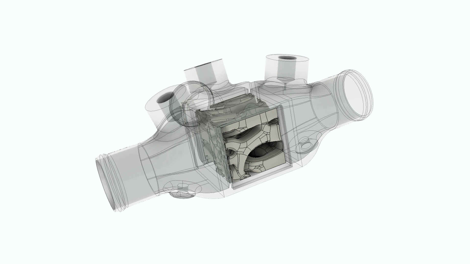
Figure 1 shows the casing of the reference cross-flow oil cooler design, as well as the available cubic design space for the optimization.

Methodology
ToffeeX is a physics-driven generative design software that enables designers and engineers to explore innovative and efficient cooling solutions. The software is streamlined to be compatible with both expert and new users, and it only requires a few inputs:
- A Design Domain, i.e., the volume inside which the software can design an optimized component;
- A set of Boundary Conditions to describe the physical phenomena involved during the optimization;
- One or more Optimization Objectives to define the goal of the optimization process.
In this project, we leveraged ToffeeX’s ‘two-fluid optimization’ feature to design the internal heat exchanger’s core, performing a simultaneous optimization of two different fluids to maximize heat transfer between them while minimizing pressure drops.
Design set-up
The design domain consisted of a cubic volume, which was then expanded to incorporate extended inlet and outlet regions, as shown in Figure 3. These regions, defined as non-designable in ToffeeX, facilitate more accurate and stable CFD simulations


The representative setup in ToffeeX’s cloud-based platform is shown in Figure 4. This figure illustrates the computational domain identified above, along with an example of how to create a boundary condition to set the values at one of the inlets.

Design optimization
As part of the design activity in ToffeeX, we explored a range of solutions by varying the weightings of the optimization objectives to identify the combinations of parameters that produced a satisfactory performance.
In Figure 5, we report some of the designs generated. From left to right, we can see how the complexity of the HEX core increases as the Heat Transfer objective weighting* is increased.

Further optimizations were then conducted with a Minimum Wall Thickness constraint to satisfy manufacturing requirements. This is a common condition for SLM printing to guarantee both structural stability and avoid leaks of fluid across the geometry (3D-printed designs typically have a higher porosity than their counterparts produced using subtractive manufacturing processes).
In this phase, we considered both a Minimum Wall Thickness of 0.8 mm and 1.0 mm to respect Nissan’s requirement.
Three different design solutions are shown in Figure 6, which represent a subset of designs generated with ToffeeX for three combinations of weights for the heat transfer (abbreviated as HT) and thickness values (indicated as Th).
Taking manufacturing constraints and performance into account, we selected the design with a minimum wall thickness of 0.8 mm and Heat Transfer weight set to 4e4. This combination yielded the best results, with the resulting design having a higher surface area compared to the others, which promoted more complex fluid patterns for both the oil and the coolant.
*The heat transfer weight sets the coefficient of the optimization function to control the relative importance of maximizing heat transfer vs. other optimization objectives – minimizing pressure loss for this project. A higher value will result in higher heat transfer at the expense of a higher pressure loss.

Figure 7 presents the selected design with the oil and coolant fluid regions colored by temperature, while Table 1 reports its performance compared to both the standard plated heat exchanger and the gyroid heat exchanger provided as a benchmark by Nissan.

Results
CFD simulations were performed by Nissan using STAR-CCM+, comparing the performance of all designs. These included the ToffeeX optimized design, which featured a benchmark design with a gyroid infill pattern and a characteristic size of 4.6 mm. These designs are compared to Nissan’s reference plate-fin heat exchanger.
| Gyroid | ToffeeX | |
| Pressure Drop Oil [Pa] | +17.4% | -87.9% |
| Pressure Drop Coolant [Pa] | +46.4% | -90.4% |
| Heat Transfer [W] | +208.9% | +54.4% |
| Heat Transfer-to-Oil-Pressure Drop Ratio | +170.6% | +1241.2% |
| Heat Transfer-to-Coolant-Pressure Drop Ratio | +170.1% | +1528.6% |
Table 1 – CFD results from STAR-CCM+
CFD simulations revealed significant performance differences between the benchmark gyroid design and the ToffeeX-optimized heat exchanger. The comparison focused on key metrics such as pressure drops and heat transfer efficiency.
Pressure Drop:
The Gyroid design exhibited a 17.4% increase in oil pressure drop and a 46.4% increase in coolant pressure drop compared to the reference. In contrast, the ToffeeX design achieved reductions of −87.9% and −90.4% respectively, indicating much lower resistance to fluid flow.
Heat Transfer:
Heat transfer improved substantially in both designs, with the Gyroid showing a 208.9% increase and ToffeeX a 54.4% increase. While the Gyroid achieved higher absolute heat transfer, it came at the cost of significantly higher pressure drops.
Efficiency Ratios:
The heat transfer-to-pressure drop ratios highlight the superior balance of the ToffeeX design. Compared to the reference, Gyroid improved the oil ratio by 170.6% and the coolant ratio by 170.1%. ToffeeX, however, achieved improvements of 1241.2% and 1528.6%, respectively, demonstrating a great efficiency in thermal performance relative to fluid resistance.
As a follow-up to the project, a different approach was attempted to further optimize the design, highlighting ToffeeX’s capabilities to enable users to explore design concepts faster.

3D printing of the selected design
The project concluded with a sample 3D printing of the selected designs using a stereolithography process (SLA) as a quick and cheap manufacturing method. These prototypes demonstrated the self-supporting geometry of the optimized design, requiring no internal support structures.
Images of the printed parts are shown below.

Conclusion
This project successfully demonstrated the capabilities of ToffeeX’s generative design software in developing an optimized cross-flow oil cooler. While the designs did not achieve the same total heat transfer as the gyroid, they achieved superior heat transfer-to-pressure drop ratios compared to conventional solutions.
Key challenges included balancing pressure constraints and maximizing heat transfer within design limitations. Future work will focus on further exploiting the available pressure drop to maximize the heat transfer.
The project highlighted the flexibility and efficiency of ToffeeX’s platform, showcasing its potential for advanced thermal management applications.
About Nissan
Nissan Motor Co., Ltd. is a global automotive manufacturer headquartered in Yokohama, Japan. Known for its commitment to innovation, performance, and sustainability, Nissan develops advanced mobility solutions across a range of vehicles—from internal combustion to fully electric platforms. The company is actively driving toward a carbon-neutral future through its Nissan Ambition 2030 vision.