Summary
Using ToffeeX, The University of Glasgow, in collaboration with the UK Space Agency, developed two novel topology-optimized rocket engine cooling channel designs for a 1 kN liquid oxygen/kerosene rocket engine that significantly outperformed conventional straight-channel cooling configurations.
The quasi-2D design achieved a 32.7 K reduction in maximum temperature while maintaining similar pressure losses, while the 3D-optimized design demonstrated a remarkable 63.3 K reduction in maximum temperature, at the cost of higher pressure drop.
This demonstrates ToffeeX’s capability to create manufacturable, high-performance cooling solutions that intelligently distribute coolant flow based on local heat flux requirements.
Both quasi-2D and 3D approaches generated unique cooling geometries that effectively manage thermal loads and reduce temperature non-uniformities compared to conventional designs. These optimized designs have been 3D printed in an advanced copper alloy to undergo hot-fire testing at the MachLab Propulsion Test Facility.

Background: rocket engines
Space launch capabilities have become increasingly critical for modern civilization. Satellites enable global communications, weather forecasting, navigation systems, and Earth observation – services that billions of people rely on daily. Scientific missions explore our solar system and universe, while commercial space stations may soon enable manufacturing and research in microgravity. This growing demand for space access requires more efficient and capable launch systems.
As launch frequency increases and new applications emerge, there is constant pressure to improve rocket performance. Better engine efficiency allows larger payloads, reduced launch costs, and expanded mission capabilities. Even minor improvements in specific impulse or thrust-to-weight ratio can translate to significantly increased payload capacity. This drives ongoing research into advanced propulsion technologies, including optimized cooling systems that allow engines to operate at higher temperatures and pressures while maintaining structural integrity.
Rocket engine cooling design
A rocket engine consists of a combustion chamber connected to a convergent-divergent, supersonic nozzle. The fuel and oxidizer are mixed and burnt in the combustor, after which the resultant gases are expanded through the nozzle to provide thrust. These high-speed combustion gases within a rocket engine can reach temperatures in excess of 3000 ºC, which presents significant challenges to the thermo-mechanical design of the system.

To achieve sustained flight, active cooling of the nozzle wall is required. Several techniques are currently employed, including film cooling, transpiration cooling, and ablative materials on the nozzle wall. However, the most common cooling architecture used is regenerative cooling, which is the focus of this project.
Regenerative cooling
Regenerative cooling involves using liquid propellant as the cooling fluid. The propellant is first circulated through the nozzle walls (between the internal nozzle wall and outer casing) before being injected into the combustion chamber. This has dual benefits, as it both cools the nozzle wall and increases combustion efficiency due to pre-heating of the fuel.
Typically, regenerative cooling channels are rectangular, with an inlet at the nozzle exit and an outlet feeding into the injector manifold. The design process must balance the channel width versus pressure loss and temperature requirements. Smaller channels will provide more heat transfer but will also lead to a corresponding increase in pressure loss.
An example of this type of cooling design is shown in Figure 2, where it can be seen that straight, rectangular channels of constant width are made at NASA via water jet milling in the work of Gradl and Protz (2019).

The standard rectangular design can be optimized to vary the channel width axially, narrowing as the propellant travels to the throat and then widening again. This variable geometry improves cooling at the throat and reduces the pressure drop compared to having a narrow width along the whole length. However, given that the majority of the heat flux occurs in the throat, it is likely that the walls outside of this region are essentially over-cooled, causing an unnecessary pressure drop.
This has posed the question: how can we implement localized cooling to a rocket engine’s high heat flux regions?
For this project, a 1 kN rocket engine has been designed that uses liquid oxygen and kerosene as the oxidizer and fuel, respectively. The aim is to design, build, and test a baseline ‘straight channel’ design, plus two ToffeeX-optimized designs, to explore how topology optimization can improve rocket nozzle regenerative cooling performance.
Designing topology-optimized rocket cooling with ToffeeX
ToffeeX is a physics-driven, multi-objective, generative design optimization software that enables topology-optimized rocket engine cooling and efficient design of many other thermal management systems.
Based on the user-supplied weightings between pressure loss and heat transfer objectives, ToffeeX will selectively add or remove material from the design domain based on the calculated performance at each design iteration. This allows cooling geometry — and hence additional pressure loss — to only be added where it is needed; this is particularly useful in applications with highly non-uniform heat flux distributions, as is the case for the rocket nozzle currently under consideration.
The design domain is formed by the space between the nozzle’s inner wall and the outer casing, and as such, it is very thin. This geometry is most tractable to 2D analysis, as in 3D, a large number of cells (~20) must be used to provide sufficient resolution in the radial direction.
In this study, both approaches have been followed to demonstrate the differences between the solution methodologies.
3D design
Figure 3 shows the design domain used. It is formed of the cooling channel envelope (which has the inlet and outlet extended slightly for computational stability) and the nozzle wall. The nozzle wall region is constrained to be completely solid, thereby accounting for the conduction of heat through the material between the exhaust gases and the cooling fluid.

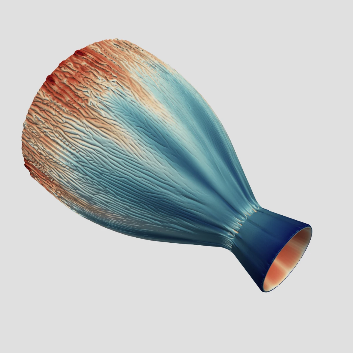
The resultant ToffeeX 3D design is shown in Figure 4. Given the limited thickness available in the design domain, ToffeeX produces ‘wrinkled’ surfaces to increase wetted area (and hence heat transfer) whilst maintaining low pressure losses, reminiscent of blood vessels in biological systems. This is first applied at the throat, where fin structures are also apparent. The surface area is also seen to increase gradually towards the combustion chamber as the exhaust gases heat the coolant flow. More effective cooling geometries are hence needed to keep the temperature low despite the lower heat flux in these regions.
Finally, at the combustion chamber end, fin-like structures are again created. Interestingly, these fins are enhanced by internal cooling channels, which increase their cooling performance.

Quasi-2D design
The above domain was used to generate a design with ToffeeX. The heat flux boundary condition was again applied in ten discrete regions. The resulting design is shown in Figure 5, where it has been projected back onto the 3D geometry.
The quasi-2D design result was simulated in 3D to provide a more accurate prediction of the design’s performance. To perform a 3D ToffeeX validation using our standard workflow, the design generated using the ToffeeX 2D solver is uploaded onto the platform as an STL into a 3D toolbox and then used to enforce a region of solid material. This accounts for a wider range of physical effects, including lateral conduction from the fins through the nozzle wall.

While the resultant quasi-2D and 3D designs may appear superficially different, their operating principle is similar. Heat transfer is enhanced at the throat and then again increases gradually along the wall of the combustion chamber as more heat is added to the cooling fluid.
In the 2D case, the geometry around the throat recovers a design close to the baseline rectangular cooling channels. Further downstream, the design distributes flow: fluid is taken from a channel running along the centreline and pushed tangentially outwards, providing localized cooling as required. As the coolant heats up — and the further removal of heat becomes more challenging — the ‘islands’ become more fragmented, promoting additional heat transfer.
Results
To compare the performance of the designs, the three geometries (baseline, 2D, and 3D) were simulated using ToffeeX.
A ‘Simulation’ run was launched within the platform to compute the steady-state physical behaviour of the system. This is useful for many reasons: benchmark designs can be simulated to give a baseline result for the optimized design, the performance prediction of 2D results can be improved, and post-processed geometries can be re-analyzed.
Figure 6 shows surface temperature plots output from these simulations, while Table 1 compares key metrics for the three designs.

Regarding the temperature plots, it is clear that the baseline design exhibits significant temperature non-uniformities. Given the constant, uniform spacing of the channels, we see that the combustion chamber is undercooled. This is likely a combination of the heating of the coolant fluid through the domain and the deceleration of the flow as the radius of the cooling passage increases.
In contrast, both ToffeeX designs successfully reduce the maximum temperature and improve uniformity, demonstrating the effectiveness of topology-optimized rocket engine cooling in managing extreme thermal loads. Whilst all three designs exhibit enhanced heating at the throat (as expected, given the heat flux distribution), the two topology-optimized designs can better manage the heating and distribution of the coolant, targeting the available coolant flow more precisely.
These conclusions are supported by the values in Table 1, which quantify the temperature reductions the two ToffeeX designs provide. The quasi-2D and 3D solutions reduce the maximum temperature by 32.7 K and 63.3 K, respectively. Similarly, the 95% temperature variation (defined as two standard deviations of the temperature field) is improved by an approximate factor of 2x and 4x.
Regarding pressure losses, the quasi-2D design gives a slightly lower pressure drop whilst providing a noted thermal benefit. In contrast, the 3D design exhibits higher pressure losses for an even greater temperature improvement. This suggests two points of note for this design case:
- Firstly, the solution time is much shorter with the 2D solver in ToffeeX. This allowed approximately three times the number of iterations to identify a more balanced design. This highlights how combining strategic analysis choices and ToffeeX can enable rapid design exploration and produce highly performant designs.
- Both the quasi-2D and 3D designs can be considered as points within the component design space. For a designer, awareness of the trade-offs and the limits of achievable designs can inform system and project-level planning. In this case, the 3D design has demonstrated a huge potential improvement in temperatures; whether this is worth the pressure loss reduction is a decision that could only be made at the broader system level.
Finally, it should be noted that the 3D design could be optimized further to reduce pressure losses if necessary.
Table 1: Baseline, 2D & 3D design performance
| Design | Pressure Loss, bar | Max temp, K | Average temp, K |
| Baseline | 4.4 | 444.6 | 355.0 |
| ToffeeX quasi-2D | 4.9 | 411.9 | 345.8 |
| ToffeeX 3D | 7.3 | 381.3 | 340.9 |
Conclusion and next steps
ToffeeX is an effective tool for extending the design capability for the conformal cooling of rocket nozzles. Rather than relying on simple geometries — which tend to be less targeted in their flow distribution — the ToffeeX optimized designs can more intelligently use cooling flow to reduce overall thermal loads and temperature non-uniformities.
The final designs are currently being 3D printed with copper chromium zirconium, a high-strength copper alloy that is frequently used in rocket engine manufacture.
The project will culminate with a hot-fire campaign at the MachLab Propulsion Test Facility, experimentally validating the performance of the straight-channel baseline and the two-dimensional and three-dimensional designs created using ToffeeX’s software.
 |  |
| Quasi-2D & 3D cooling channel designs on the printed part. | Conventional & quasi-2D channel designs on the metal print. |
About the University of Glasgow
The University of Glasgow has a longstanding reputation in aerospace engineering, with over 60 years of research. The Division of Aerospace Sciences is internationally recognized for its expertise across various areas, including aeronautics and aerospace systems. The university’s research themes encompass Intelligent & Autonomous Systems; Aerodynamics, Fluid Mechanics, Flight & Flow Control; Dynamics, Avionics, Navigation & Control; Space & Exploration Technology; and Modelling & Simulation.
About the UK Space Agency
The UK Space Agency inspires and supports the UK’s space sector, driving growth, innovation, and collaboration across academia, industry, and government. It enables world-class space science, technology development, and commercial opportunities, helping position the UK as a global leader in space.