Following the initial design project of a cross-flow oil cooler for Nissan, we decided to explore two new design approaches to further optimize its performance, while also showcasing the software’s flexibility in exploring different design alternatives.
- Patterning a unit cell design
- Optimizing and stacking individual layers
Patterned unit cell approach
Firstly, we attempted to maximize the performance of the design by halving its size in all directions. We then created a 4×2 core repeating the obtained design, mirroring the geometry to ensure a consistent flow for both the oil and the coolant, as shown in Figure 1.
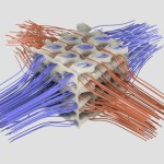
The heat exchanger core, with the oil and coolant fluid regions colored by temperature, is displayed in Figure 2.


Layer-by-layer design optimization
Another approach we considered was to optimize only a layer of the available design domain and then stack all the layers on top of each other to fill the heat exchanger core.
We considered three different alternatives, going toward a progressive reduction of the layer thickness:
- Optimization with 3 layers
- Optimization with 5 layers
- Optimization with 10 layers
The setup and results are reported in the article that follows.
Optimization with 3 layers
For the first approach, we identified a layer with a thickness equal to 8 mm. This allows to fill the cube with three optimized layers interspersed with three solid layers of 1.167 mm of thickness.
The design space and the best-performing design are shown in Figure 3.

After performing the optimization, we stacked the layers together to build the heat exchanger core. An illustration of the heat exchanger core is reported in Figure 4. In the same figure, the fluid regions for the oil and the coolant are reported.

Optimization with 5 layers
Following the approach in the 3-layer design, we considered an even smaller design space with a thickness of only 3.92 mm. This allows for a resulting core of 5 layers, interspersed with four solid layers of 1.975 mm.
We report the results in the following sections, as shown in Figures 5 and 6.


Optimization with 10 layers – 2D extruded design
Finally, we chose a very thin design domain of 2 mm only. This would result in a total of 10 layers, each divided by a solid layer of 0.8 mm.
Given the reduced thickness, we opted for a different optimization methodology, which is available in ToffeeX. This is an example of applications that are well-suited for simplification and subsequent analysis as a 2D problem. In essence, any scenario in which flow is largely planar is potentially suitable for dimensional reduction.
ToffeeX allows the user to perform 2D optimizations and analyses by setting up a so-called 2D Extruded Design Optimization.
This has the benefit of reducing the complexity of the resulting design to a geometry with a planar shape and then extruding to account for the thickness.
For this optimization approach, it is not currently possible to perform a simultaneous optimization of the two fluids. Given to scope of this follow-up activity, we performed a design optimization with only one fluid. We optimized the oil layer and applied the design obtained for both the oil and the coolant layers in the assembly, rotating the geometry by 90 degrees and alternating the different layers.

The optimization objectives chosen were ‘Minimize Temperature’ and ‘Minimize Pressure Losses.