Across five production projects — with IKM/Equinor, CERN, Nissan, UniBo Motorsport, and Komatsu/SSAB — ToffeeX’s physics-driven generative design produced thermo-fluid geometries that expert engineering teams could not have drawn by hand, and that beat even sophisticated AM patterns like gyroids. In every case, additive manufacturing is what turned the physics-optimal shape into a real, buildable part. The results aren’t 5–10% better. They’re a different category: 50% lower LNG measurement variability, a 15× better heat-transfer-to-pressure-drop ratio, a 52% lighter manifold designed in 5 hours instead of weeks.
The Real Ceiling isn’t Simulation. It’s Design.
Intuition has limits.
The solution space for a complex thermo-fluid component is too vast for any human to explore in a reasonable timeframe. That’s when you combine tight performance targets, manufacturing constraints, and the raw complexity of fluid dynamics; you’re not just solving an engineering problem, you’re looking for a needle in a multidimensional haystack.
Here’s the pattern that we often see with our customers: skilled engineers, a solid CFD stack, a clear performance target, and a wall they can’t get past.
That wall is rarely simulation speed. It’s that you can only simulate what you’ve designed, and you can only design what you can conceive. When the best geometry for a problem is something no human would draw, and no pattern library would suggest, the traditional CAD-then-CFD loop simply has no path to it.
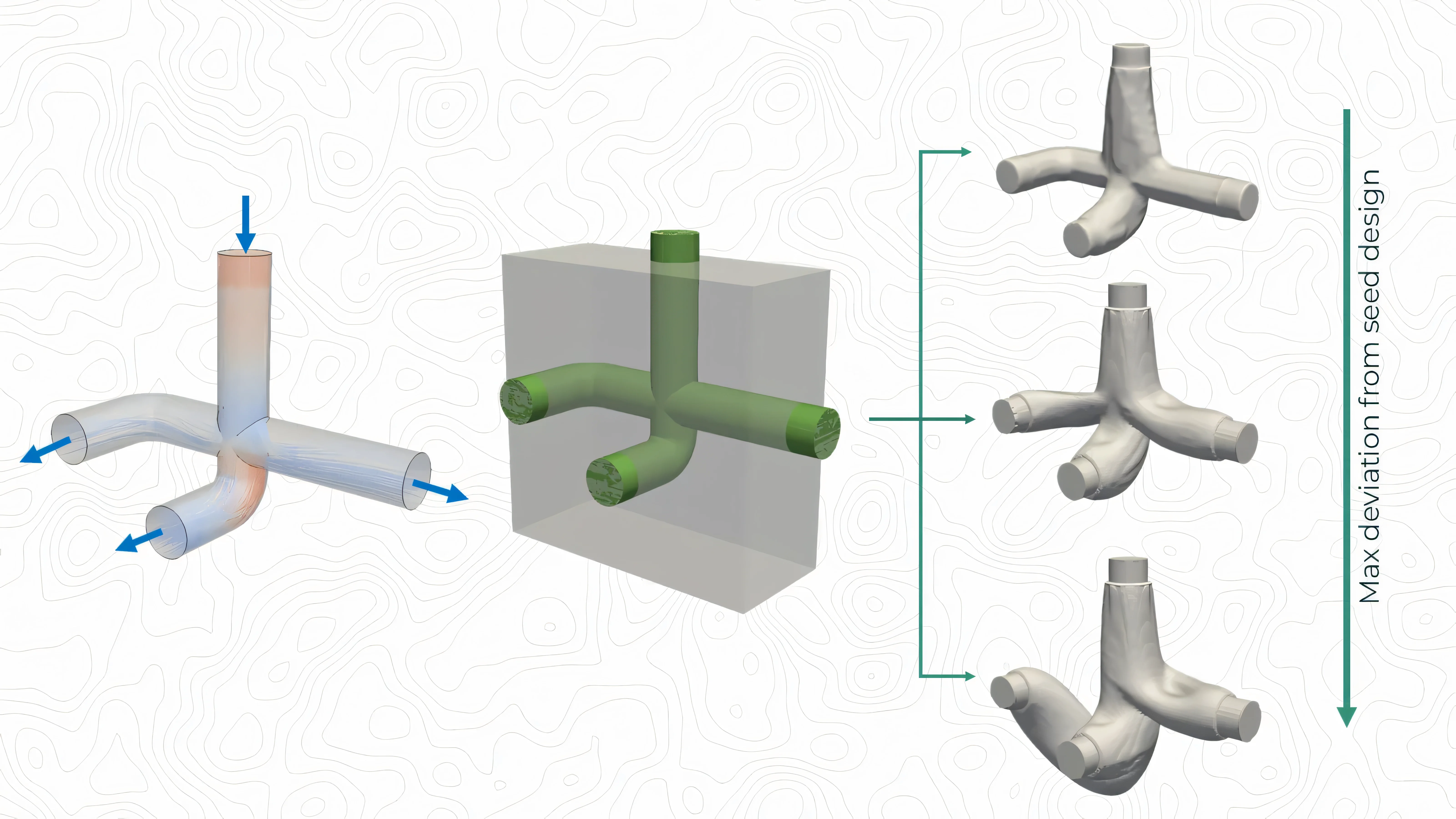
Physics-driven generative design inverts the order. You define the physics — boundary conditions, performance objectives, and manufacturing constraints — and the Navier-Stokes and heat-transfer equations generate the geometry from scratch.
Below are five cases where we handed the physics the controls. The results weren’t just better than the baseline. In several instances, they were better than what an expert team would have attempted in the first place.
The LNG Vaporizer That Had to Be Perfect in the Arctic
Customer: IKM Flux — Equinor Hammerfest LNG Terminal, Norway

LNG custody transfer is a precision game. When liquefied natural gas changes hands — at a terminal like Equinor’s Hammerfest facility in Arctic Norway — every fraction of a percent in measurement accuracy has direct financial and compliance implications. The key metric is Gross Heating Value (GHV): the energy content of the gas. You need it to be right, consistently, across varying flow rates and ambient temperatures.
The existing vaporizer design was functional. But in conditions like Hammerfest, “functional” isn’t enough when commercial accuracy is at stake.
IKM Flux brought ToffeeX in to redesign the internal thermo-fluid architecture from scratch. The objective was to find the geometry that best ensures complete, uniform LNG vaporization while simultaneously managing heat ingress, pressure drop, and cold ambient losses.
ToffeeX ran through multiple optimization iterations, each one building on the last: first maximizing convective heat transfer with a spiral flow path to extend LNG residence time near the heater; then front-loading thermal energy toward the inlet to drive earlier phase change; then introducing vacuum insulation cavities to account for Arctic ambient losses; finally integrating lattice structures in non-functional regions to reduce weight and build time.
The final design is a single monolithic component, entirely self-supporting, with powder evacuation channels and structural reinforcements baked directly into the geometry. It was printed in AlSi10Mg on an EOS M290 by Valland.
At Equinor’s Hammerfest terminal in March 2025, field testing confirmed a 50% reduction in the standard deviation of GHV readings across all tested flow rates up to 1200 SL/hr.
No engineer would have drawn that spiral. But the physics did.
🔗 Read the full IKM vaporizer case study →
The Cooling System That Replaced Two Components With One
Customer: UniBo Motorsport & BI-REX, Italy

Electric racing motorcycles are a thermal management nightmare in a very small package.
The UniBo Motorsport team, competing in MotoStudent, a championship that rewards exactly the kind of engineering ambition that defies conventional design, needed to solve a classic thermal challenge: simultaneously cooling the inverter electronics and the motor cooling circuit, in a component that had to fit inside a racing motorcycle.
The conventional approach would have been two separate systems. Maybe three components with heat exchangers, plumbing, and assembly joints that each carry their own weight, their own leak risk, and their own thermal compromises.
Instead, ToffeeX generated a topology-optimized integrated tank and cold plate: a single component that handles both functions simultaneously, using dry ice sublimation as the primary cooling medium for race sessions.
The optimization ran two separate physics domains — forced convection for the inverter cold plate, natural convection and conduction for the dry ice tank — and coupled them with realistic boundary conditions at the interface. The result was a geometry that no conventional manufacturing process could produce: organic internal passages, integrated structural features, and no assembly joints.
Manufactured by BI-REX via selective laser melting, the final component dissipates nearly 895 W of thermal power in a package compact enough to install in a race motorcycle. Testing confirmed that in its optimal operating window (7.65–10 L/min), the design reaches the physical limit of the cryogenic boundary condition, not the hardware itself.
From requirements to race-ready component: approximately two months.
🔗 Read the full UniBo motorsport case study →
Nissan’s Oil Cooler: 15× Better Than the Starting Point
Customer: Nissan Motor Corporation, Yokohama, Japan

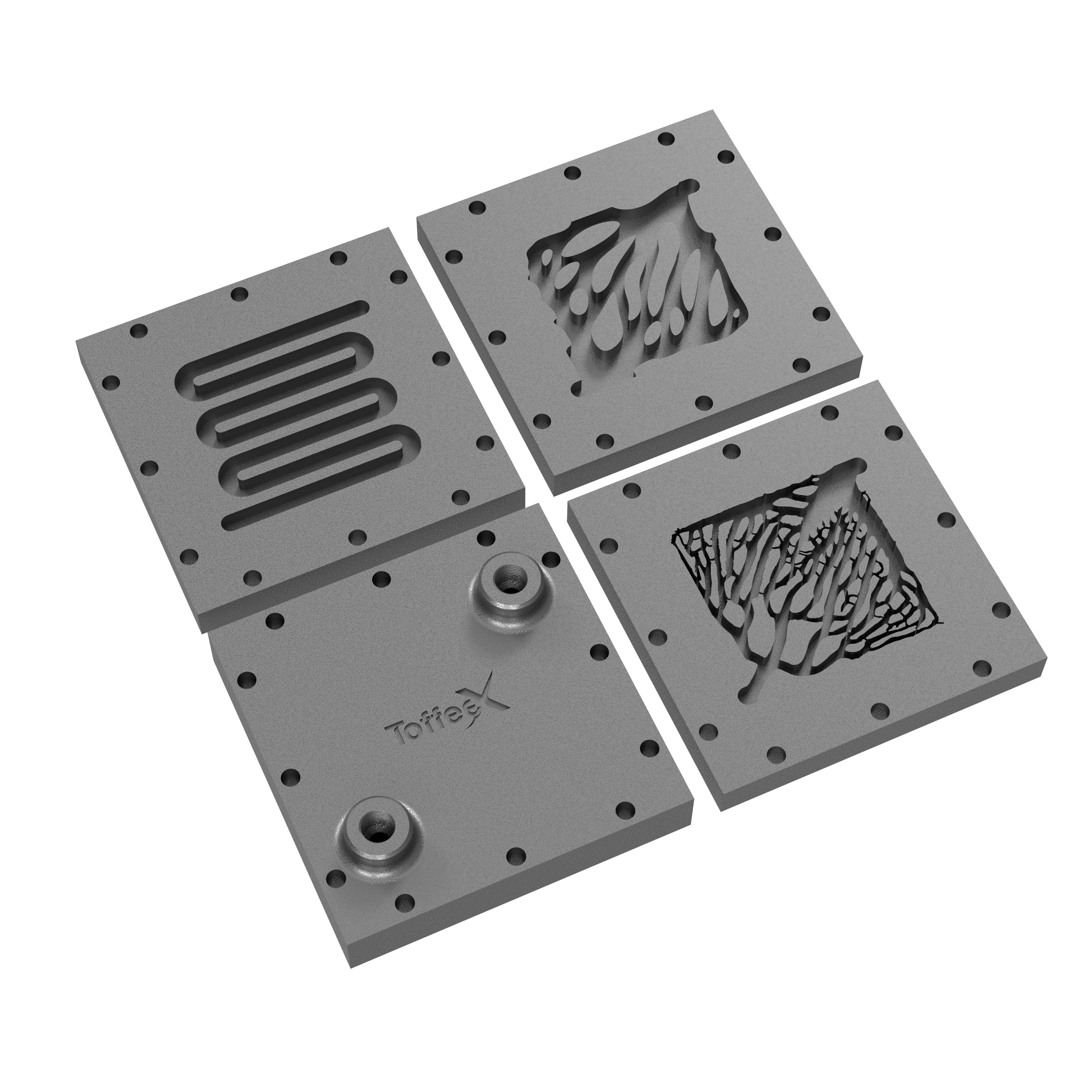
When Nissan brought ToffeeX in to redesign an oil cooler for powertrain systems, they benchmarked the output against two alternatives: a conventional plate-fin heat exchanger and a gyroid TPMS lattice structure.
The gyroid performed well in raw heat transfer, achieving a 208.9% improvement over the reference. But it came at a steep cost: oil pressure drop up 17.4%, coolant pressure drop up 46.4%, well above the prescribed limits. Gains on one axis, significant losses on another. A classic engineering trade-off.
ToffeeX approached the problem differently. Instead of chasing maximum heat transfer in isolation, the optimization simultaneously minimized pressure drop across both fluid channels while maximizing heat transfer. A two-fluid topology optimization problem (a unique feature of ToffeeX) that explores the design space in ways that sequential CFD loops simply cannot.
The heat transfer-to-pressure-drop ratio came in at 1241% better than the reference for oil, and 1528% better for coolant. The ToffeeX design was also fully self-supporting for SLM printing. No internal supports required, minimum wall thickness constraints respected.
🔗 Read the full Nissan oil cooler case study →
Komatsu’s Hydraulic U-Bend: Quick Optimization for ToffeeX with Maximum Results
Customer: SSAB & Komatsu, Sweden / Japan

A hydraulic U-bend doesn’t sound glamorous. But in heavy-duty machinery, hydraulic efficiency directly drives fuel consumption, thermal load, and operating costs. Every Pascal of unnecessary pressure drop is energy wasted, heat generated, and efficiency lost across a machine’s entire lifecycle.
The existing U-bend design for Komatsu’s machinery worked, but it was heavy and inefficient at the corner, exactly where momentum changes direction and where bad geometry creates turbulence, velocity gradients, and recirculation zones that rob efficiency.
SSAB and Komatsu partnered with ToffeeX to explore what a physics-optimized U-bend could look like when you impose AM constraints but remove the geometric limitations of conventional machining or casting.
The ToffeeX design featured smooth, organically shaped internal turning vanes near the outlet, achieving a 25% reduction in pressure drop (from ~355 kPa to ~260 kPa) and a 40% reduction in material usage.
🔗 Read the full SSAB/Komatsu case study →
CERN’s Manifold: 5 Hours, 52% Lighter, Built for the Edge of Physics
Customer: CERN / University of Bath — CMS Inner Tracker Upgrade, Geneva

If there is one environment in the world where “good enough” is not an engineering philosophy, it is CERN’s Compact Muon Solenoid detector. The CMS Inner Tracker reconstructs particle trajectories nanoseconds after each high-energy proton collision. The electronics involved are sensitive enough that even a few degrees of thermal deviation can compromise measurement precision.
For the Inner Tracker upgrade, CERN needed CO₂ cooling manifolds, a compact component with one inlet and eight outlets, delivering uniform CO₂ flow at high pressure (design pressure: 186 bar) while keeping mass below 119 grams and pressure drop below 1,200 Pa. CO₂ cooling is inherently complex: high pressure, low temperature, and the kind of intricate internal flow paths that are physically impossible to manufacture without additive manufacturing.
Conventional CAD tools couldn’t generate the internal geometry. Manual design iteration would have taken weeks.
Nadya Collantes from the University of Bath used ToffeeX to define the design domain, input the boundary conditions, and let the platform run. The optimized manifold was ready in 5 hours of engineering time.
The results: pressure drop at 850 Pa — 29% below the benchmark. Mass at 57.1 grams — 52% below the original 119g target. Outlet velocity variance within specification across all 8 outlets. Fully compliant with 3D printing requirements in 316L stainless steel.
Five hours. For a component destined for one of the world’s most precise scientific instruments.
🔗 Read the full CERN manifold case study →
Why Additive Manufacturing Makes This Possible
These five cases span energy, motorsport, automotive, heavy industry, and particle physics. The thermal challenges are different. The operating environments are radically different. The fluids (LNG, dry ice, CO₂, engine oil, coolant, high-pressure CO₂) couldn’t be more varied.
But there’s a pattern worth noting: in each case, the geometry that ToffeeX identified would have been extremely difficult, or impossible, to manufacture without 3D printing. The spiral paths in the LNG vaporizer. The integrated dry ice chamber and cold plate were produced as a single SLM part. The smooth, organic turning vanes of the Komatsu U-bend. The multi-outlet manifold geometry for CERN’s detector.
Generative design and additive manufacturing work best as complementary capabilities rather than independent innovations. One finds a geometry that conventional design methods might not surface. The other gives you a realistic path to building it.